"So...I want power steering to my Monster Miata. Do I use a Ford Power steering pump or somehow adapt the Mazda one?"

This question comes up fairly often. There are advantages and disadvantages to each approach but the Mazda pump usually wins out due it's lighter weight, it's compatibility with the existing Miata steering rack and the fact that most people would rather deal with modifying a bracket rather than a power steering hose. The decision basically comes down to which you'd rather deal with...plumbing or fabrication.
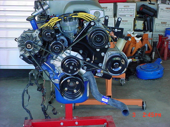
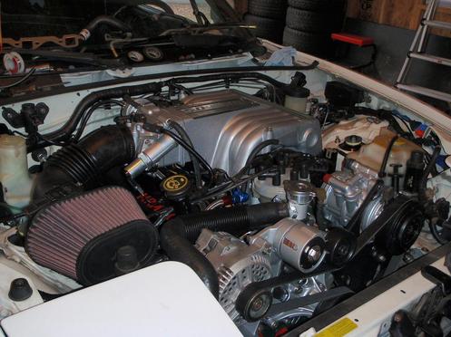
First let's look at option # one: using the Ford pump. Above is a 1987-93 Ford Mustang 5.0 wearing it's "stock" belt configuration and Ford power steering pump. It is possible to use this exact set up in a converted Miata although doing so will entail "notching" the driver's side frame where the PS pump protrudes and making up two custom hoses to mate the pump with Mazda steering rack. While both of these are both not out of the realm of possibility for the average builder I've always felt using the Mazda pump was a more attractive option. I'll explain why below:
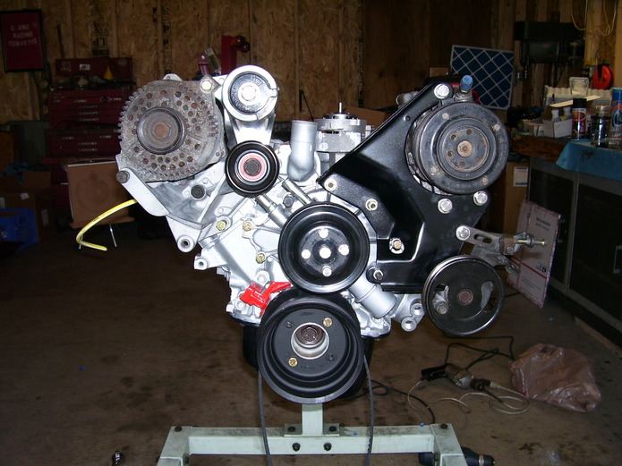
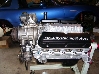
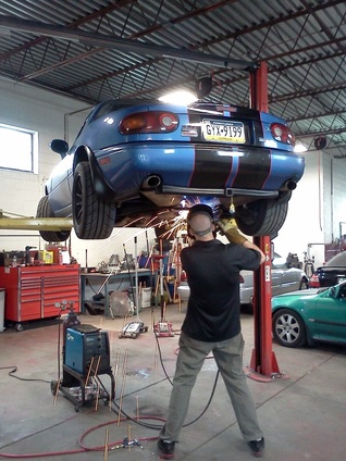
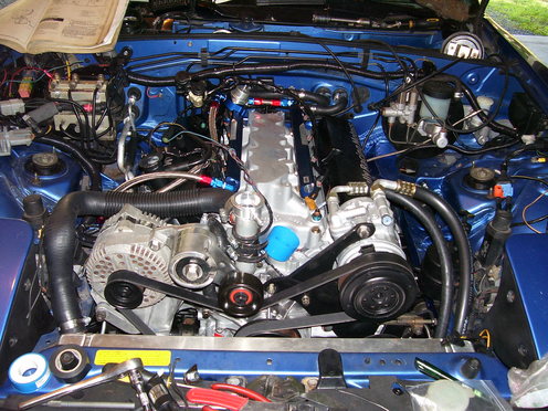
This is the engine currently in my blue Laguna during it's mock up. On this and the car before it I used the Mazda power steering pump as can be seen above. The obvious first advantages over the Ford unit is the size and location. While the Ford unit is about the size of a melon, the Mazda unit is only about the size of a fist. It's smaller size and remote reservoir bottle allows it to be tucked nicely inboard clearing the frame rails (no need to cut and weld). Because it is matched to the Mazda rack you can get away with using the stock lines without modification (you can even leave them hooked up to the rack during the conversion if you are careful) and it will never overpower the rack with too much pressure. From a purely cosmetic point of view I tend to think it's a little less ugly than the Ford unit as well. As you can see in the installed pictures above it's barely visible in the completed engine bay:
There are no modifications needed to the Ford PS/AC bracket to make the above work. The power steering pump and Mazda tentioning bracket almost magically mount up to the same two holes in the Mustang AC/PS bracket that the original Ford pump used. With the addition of a small spacer (I use an old Mazda seat belt tower spacer - if you installed a roll bar in your Miata you'll have four of them lying around - a set of washers or even a small section of pipe would work fine as well) you can pass the main power steering bolt through the hole mounted behind the pump's pulley (the one you need to orient the pulley correctly to access), through the Ford PS/AC bracket's lower PS mounting hole and right into the small aluminum AC/PS bracket on the driver's side head. The Mazda tentioning assembly bolts to the upper Ford mounting hole with a generic bolt and nut. Slightly grinding the end of the Mazda tension arm will allow the pump to be pulled in even closer but is not completely necessary. There is also a bracket spot welded to the Mazda tension arm that is no longer needed. I usually take ts off with a grinder to make things look cleaner but again this is not completely necessary.
"Um, I think we have a problem..."
If you've looked at a Miata pump next to the Ford parts you've probably realized by this point that while the Mazda pump uses a four-rib serpentine belt the Ford belt is six-rib. Unfortunately this is really the only "difficult" aspect of using the Mazda pump as compared to the Ford unit. To make it work you'll have to run a second belt (a 35.5" 4-rib belt) behind the Ford's serpentine belt. To power it you'll have to modify the Ford's crank pulley by adding a second 4-rib sheave (the part of a pulley the belt contacts) behind the existing 6-rib sheave. Fortunately luck would have it when you cut out the center of it a 1994+ Miata water pump pulley has exactly the right internal diameter to slip right over the back portion of a 1987-1993 Ford Mustang crank pulley where it can be carefully tack-welded in place.
Since most builders do not have the equipment to handle this type of job its recomended that you take your Ford crank pulley and 1994+ Mazda water pump pulley (note that 1990-93 ones are designed for a v-belt and will not work...sorry) to a machinist and have the lathe and welding work done. If you don't have a local machinist who can do the work McCully Racing Motors can get the pulley done for you even if you do not have one or both of the needed core pulleys.
Below are a few images of the completed assembly. Click on any one of them to open them up in a bigger window:
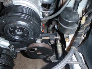
Here we can see the Mazda tension and mounting unit from above. Note that the power steering reservoir will need to be moved back a few inches to clear the adjuster arm. The body-mounted tab a couple inches in front of the reservoir was the original mounting point.
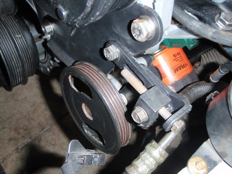
A closer look at the Mazda tension arm/PS mount bolted to the Mustang AC/PS bracket. The only modification to what you see below was to grind down the inboard end of the rear portion of the tension unit to allow it to move closer to the Ford bracket during belt mounting. The two bolts that are part of the tension mechanism are original Mazda bolts while everything else in the picture is aftermarket stainless.
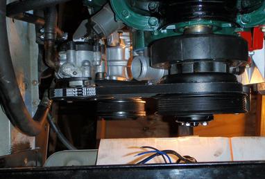
Here we can see the modified pulley from below. It's amazing how well everything lines up. While not directly related to this project, its worth noting that I typically remove the Mazda power steering cooling loop from the system to make more room for the radiator. To eliminate the loop I cut the lower PS hose (return, not pressure) into a "u" shape and run it directly from the pump to the reservoir. The hose attached to the pump with two hose clamps is this hose.
A final image of the pump form the side during mock-up. If you look closely you can see the spacer used in front of the pump (a seat belt spacer) and the threaded area of the bolt threaded into the Ford aluminum rear AC bracket. Note that another small spacer is used here when actually installed.
I hope you've enjoyed this write-up. If you have any questions please feel free to post your question here, at the V8Miata Forum or via email at [email protected].
-Jason
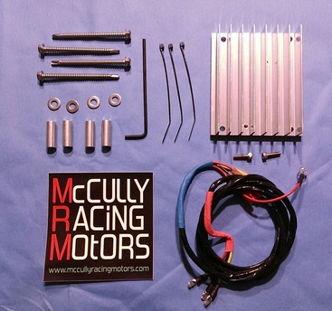
Here it is, our new TFI Relocation Kit. The main area of improvement is the heat sink itself which has been upgraded from the reclaimed Ford block of cast aluminum we used to scrounge junk yards for to the all-new, custom extruded aluminum piece you see to the left.
The heat sink is still supplied with an application of ArticSilver 5 Silver Heat sink compound but now also includes a few more improvements to help make the installation easier for the average customer. They are:
1. Everything is All-Weather Proof - We are located in the NorthEast where winter road salt turns most aftermarket accessories disgusting looking within a few winter months. We hate rust. To that end every component of the kit is ether aluminum or stainless steel.
2. No Special Tools Required - We don't think you should have to know how to solder or need to cut and crimp wires to install this kit. All you need is a small drill bit for the mounting screws and a wretch to screw them in. We even included a set of M4 stainless cap screws and an allen key to replace the Ford module bolts that require that special TFI tool. Don't worry, we can rent you the TFI tool from us for $15 so you can get your old module off. Once you use the included cap screws you'll never need it again so send it back within 30 days and we'll refund $13 back to you.
3. Improved Heat Dissipation - Back in grade school we learned that heat rises. Despite this, Ford designed their heat sink in such a way that the TFI Module's heat would have to travel down and then sideways to the fins to be dissipated. We designed the new heat sink with an "underslung" module mount that mounts the module upside-down under the heat sink so that heat can rise naturally from it and directly to the fins above for dissipation. As an added bonus the underslung design also better protects the module from puddling water. Water is the only other thing we've found to adversely affect TFI modules on our shop cars.
4. Same Price - We did not want to have to raise the price for our kit. Through a ton of supplier research we were able to do just that. We did however find that printing out the now much longer installation instructions for each order would kick the price up. To that end we've uploaded the 5 page manual to our website for handy downloading. The upside of this is that you can now download the instructions before buying to see if it's something you want to handle before making a purchase.
We're very happy with the way the kit turned out and can't wait to see them fly out of our shop. Click on "TFI relocation" on the right side of the blog to read about the development of these kits over the last few months and visit our website to order and read more.
-Jason
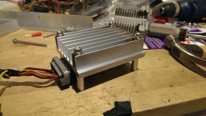
What you're looking at is the first production prototype of our new TFI heat sink kit. Although it looks ready to go I'm still planning on making one last additional small upgrade before they are ready to go. I went to great pains to make sure that, unlike other aftermarket accessories, this part looks the same a year after it's installed as it does the day you put it in. To that end I've sources all rust-free components (aluminum heat sink and standoffs, stainless steel washers and attachment screws). The only part that could rust and look bad are the stupid little M4 hex-head screws that Ford used to attach the module to the heat sink. I'd hate to see little rust streaks from the back side of those screws leaching out after a few years.
So....
I decided to include in the kit new stainless steel M4 screws. The problem is that no one makes a stainless steel copy of the Ford screw. I looked at a few possibilities and decided my best bet was to use Allen-head cap screws. Keeping with my no special tools rule I decided to include a 3mm allen key in the kit in case the customer does not have one. Both of these new components have been ordered and should be here next week sometime, at which point I hope to have the online and printed instructions ready. Shortly after that the fist of these kits (its already been purchased) will be ready to ship out.
Thanks every one for your patience as we redevelop this product. Remember, if you want to place your order at any point before the kits are ready to ship you'll get your kit in order as they are finished.
-Jason
Its Finally Happened-
The demand for our popular Ford TFI relocation kit has exceeded our ability to pick Ford heat sinks from junk yard F150 pickups. We thought this would eventually happen but sort of didn't think it would be for a while. We never thought that with only web site advertizing we'd be moving 100 kits a year but now that we are local junk yards can't keep up.
Since the start we thought that an alternative to the reclaimed Ford heat sink could be made using computer-grade components. We've been looking into it from the start but never moved on it since we seemed to have enough yard heat sinks available. The fact that we can't get enough used heat sinks means now is the time to move to this new heat sink.
Here at McCully Racing Motors we don't just settle for "that'll work". We were not going to move to this new heat sink until we could be sure it could be as plug-and-play as the "old" kit.
With that in mind we've close to offering a new kit that will:
-Include all needed parts including a "serving" of Artic Siver 5 thermal grease.
-Offer actual improvements over the old kit's major weakness: it's reliance upon a "afterthought" Ford heatsink. The old heat sink was not the most thermally efficient design and also allowed water to get into the access door of the module if not placed in a moisture-free location. Both of these issues are addressed in our new design heat sink.
-Require no soldering, wire crimping or special tools other than the Ford TFI removal tool (read more about this tool below BTW).
-Work with our existing weather sealed and RF shielded harness.
-Be cost effective at the same price as the old kit (no price increase).
We are about two weeks away from releasing the new kit. Unfortunately we are out of old style heat sinks and can not fill any orders after 2013-12-01 with them (if your order has already been placed it is covered and will ship shortly). If you'd like to place an order for the new kit before its release please feel free to do so, you'll be first in line when they are ready to ship.
Regarding that special tool- we ordered three of them from an online Mustang supplier and are debating "renting" them to customers who do not have access to one. The cost would most likely be an additional $12 over the cost of the kit, $10 of which would be refunded if the tool returns to us within 30 days. We're looking in to adding this when we upgrade the kits on the website.
As we did with our harness upgrade last year we'll offer a "heat sink only" option for any existing customers who want to upgrade to the new heat sink and keep their existing harness. We'll have pricing available when we update the website.
Thanks everyone, we'll keep everyone updated about this change,
-Jason and Thomas McCully
At Del-Val Miata clubs annual friving school we mounted a GoPro to the nose of our 331 c.i. V8 Miata. Here's what we got...
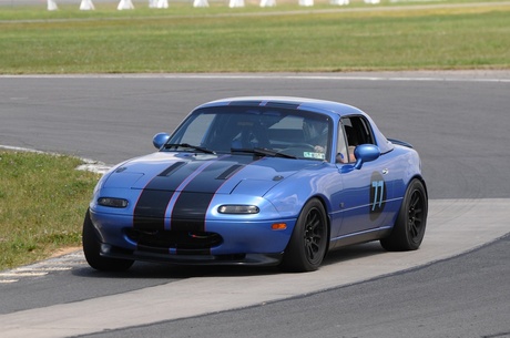
The next video shows four laps of Pocono during the same event from inside the car. The car is a 331 c.i. (5.4 liter) Ford-Powered Monster Miata built by Thomas and Jason McCully of McCully Racing Motors. The car is a daily driver when it's not snowing and has ABS, air conditioning, power steering and a full interior.
The engine has a 331 Scat forged stroker kit with H-beam rods and dome pistons. The heads are Explorer GT40 irons (soon to be replaced with something a little less suffocating). The intake is an Explorer GT40. The engine is controlled via a MegaSquirt 2 standalone engine management system. The suspension is a VMaxxx "Track Pack" from Flyin' Miata, the wheels are 949racing 15x8 6UL's and the tires are 225/45-15 Nitto NT01's. The brakes are Wilwood Dynalite calipers on the front over 1991 VW Corrado rotors and stock 1994 Miata calipers and rotors on the rear. The pads are Hawk "Blue" all around. The car weighs about 2700 pounds.
The video was shot with a GoPro Hero Motorsports camera purchased used on eBay. It's mounted upside down to the cross bars of the roll bar using a homemade mount.
The music is "Jaan Pehechaan Ho" by Mohammed Rafi as performed in the 1965 Bollywood film "Gumnaam." It was later used in a second movie, "Ghost World" in 2001 and most recently a 2011 Heineken ad.
I've long wanted exhaust cutouts on the car for the track. The Borla ProXS mufflers I had installed originally are great in that they are very quiet at idle, cruse and even under light throttle. They really only open up at full tilt and even then they are not so loud. this is great for 99% of the driving I do with the car, I've always felt that "loud" is really only fun for a week or so. My first build I used Flowmasters and could not stand it after a few weeks. It did sound good when you wanted it to though.
And that brings us to the way the car is now. It's quiet, but I was getting tired of turbo Miatas out basing it at the track and at meets. I also hated how the audio on my in-car GoPro videos contained more sound from the suspension and the passenger seat belts clanging that the exhaust. I actually purchased a set of cut outs from Summit only to find that there was no space anywhere to locate them on the exhaust system. I had to figure out a different way.
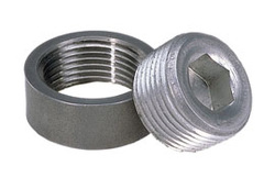
My first plan was to buy a set of 4 oxygen sensor bungs and caps and have them welded in in different spots on the system so I could "tune" the sound by taking out one or two at a time. I though about this and became afraid the sound would be too "poppy" due to the small diameter of the bungs. I wanted something a little larger in diameter. While searching I happened across a 1" NPT oil pan inspection bung and plug made by Moroso. I picked up a set and had Epic Tuning down the street from me weld them in.
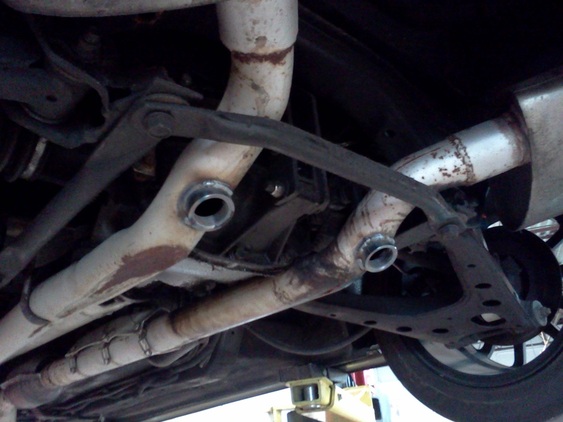
Here's the result. The "ports" are pretty big in comparison to an oxygen sensor bung and they are located where I can pull them out while changing my rear wheels for a track day. We started the car up before sticking the plugs in and the sound was actually quieter than the Flowmasters I had back in the day. It was actually quiet enough I could actually keep them out on the street. We'll see how they make the car sound at the track on Monday.
It may have been due to the rather stagnate, miserable, and disgusting weather we had today but none of our family of friends had any type of July 4th activity planned today. It was just as well as the weather was very miserable and it gave me the chance to try some ideas out I've had for my track wheels.
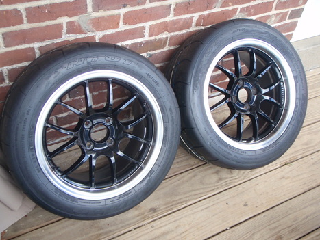
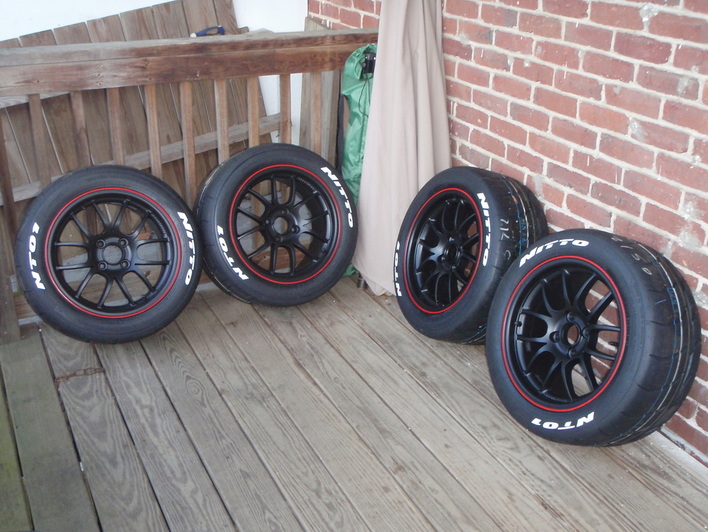
Here they are (or two of them at least), a set of four "original" 949Racing 6UL's. They are actually quite rare in a way since 949 only produced this first batch for a little over a year and then moved on to the second generation ones. These were the only ones that ever came with the machined lip and colored center. I like the look, but I kind of feel I want them to match my street wheels, a set of TireRack C1's which are matte black. I also intend on selling these at some point and really don't want the original finish to be damaged any further from dust from my track pads. To change their look, and protect them, I decided to give them a shot of PlastiDip. I also wanted to try painting the lettering on the tires. I'd actually experimented with using white PlastiDip on my street tires which did not turn out as well as I planned. They looked good when I put them on but the first time I went over 45 mph the letters literally just flew off.
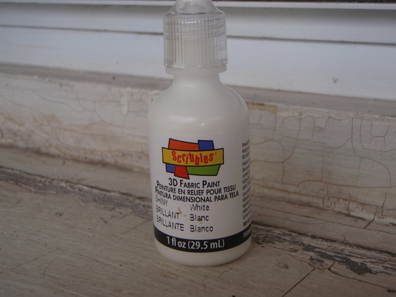
For this attempt I decided to try something new. I'd stumbled across a post somewhere by a guy with a Factory 5 Cobra. He, after trying a number of paints, finally tried fabric paint, the puffy type used to paint T-shirts. I figured if it's designed to withstand washing and drying and still stay flexible maybe it would work. I picked up three little bottles of the stuff above for $1.37 each at the craft store.
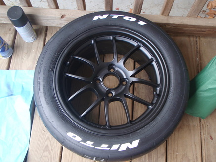
It actually worked pretty well. It has about the consistency of Elmer's Glue so you sort of just let it float on thickly and make a little pool in the letters. The first one tire took me about half an hour but the rest went much quicker. The PlastiDip turned out nice as well I think. Hopefully it will still be removable after being subjected to the track.
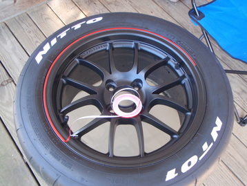
I liked how they turned out with the PlastiDip and white letters but I still felt they lacked something. It turns out I still had a little of the red pin striping left from when I redid my stripes a few years back. I'm not sure how well it's going to stick to the PlastiDip but I do like how they turned out in the end:
We'll see how they hold up on the track. I may add the stripe and white letters to my street tires if they hold up here. All-in-all not a bad two hour's work.
-Jason
Last year at the track we had a great time. It was the first year with the fans located behind the radiator as "pullers" which seemed to completely cool the car down on the street even with the AC on. The hood vents helped even further and even seemed to pull the car down o the track a bit more at speed. We added a set of side air dams and door bars, both of which changed the cars feel and appearance dramatically. We even upgraded to Evan's waterless coolant.
We really hoped this would be the year that the car would be "unlimited" and that we would both find our driving to be the limiting factor, not the car. Keeping the thing cool had been a continual battle the two years before that it had been tracked but now it seemed to be fine on the street so the track should have been a piece of cake, right?
The car was great for about 10 laps until we started to see the temps rise. I had installed an electronic AutoMeter gauge (much more accurate than the Miata dash gauge) and noticed it climbing up past 220 degrees. I kept at the throttle and it kept climbing up past 250, the limit of the gauge. I found that if I throttled it back a bit, threw the car in 5th and took a "rest lap" the temps would come back down and I could jump back in the fray. Needless to say, this is not ideal.
I took the winter to try and figure out what went wrong. I figured the shroud I had made for the radiator was too restrictive at speed. The ironic part is that with the fans in front of the radiator as "pushers" (the original configuration) the stock gauge would never show an issue on the track. On the street the car would overheat the moment you put the AC on. With the shroud the situation was reversed, fine on the street, hot on the track.
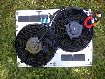
So I set about redesigning the shroud. I purchased two new TriPac fans from Monster Miata (the original ones were almost seized-maybe contributed a little to my overheating issue...) and a set of "Pressure Relief Flaps" from Spal that should let the air pass through the shroud at speed but still seal it up when the fans are on. I also integrated two new high-amperage relays into the shroud itself and built a small harness and plug for it so that everything would be easy to remove.
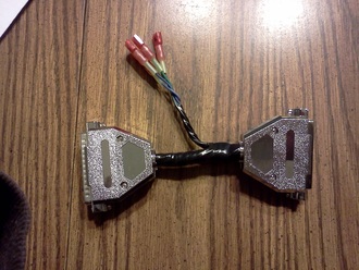
Earlier this year I removed the original unmodified or chipped A9L ECU and swapped in a MegaSquirt II PNP unit from DIYAutotune. Originally I had my fans running of a Miata thermoswitch that was placed in the Ford thermostat housing neck.. One of the reasons I went with the MSII was it's ability to run fans via the ECU's coolant temp sensor. To hook it up I made this small adapter harness on the left. The harness goes between the MSII and the Ford harness adapter and breaks the four unused idle wires out so I can use them.
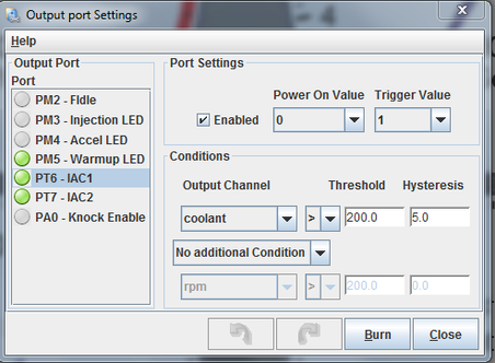
It's just amazing the freedom a programmable ECU gives you over a stock unit. Using TunersStudio I configured the MSII to turn the fans on at 200 and off at 195. Set up like this I get a consistent 198-210 degree running temp even with the AC on. We'll see if it keeps those temps at the track.
Oh, and on a side note regarding the 250+ temps on the track last year via my Autometer gauge and the "normal" readings on the stock gauge the year before: Currently Tuners Studio is showing that my Autometer gauge is running consistently 15 to 20 degrees higher than what it is showing. I'm not sure if this is a problem with the gauge or the ground to it but chances are my temps last year were more like 230, not 250. As far as the stock gauge is concerned, I read at a few different sources on the web that the stock gauge is set to show "normal" at anything between 150 and 210 degrees. The first half of the gauge is the 0 to 150 section, the needle hardly moves at the center between 150 and 210 and the last half of the movement covers 210 to 240. Knowing this it's highly possible my actual temps the year before were possibly in line with what I saw last year as well.
-Jason McCully


 RSS Feed